 Help
Help
Back to configurator app
Introduction
The purpose of this app is to give a proof-of-concept (POC) for an industrial whitespace configurator. This POC is done in the form of a web app designed to aid in the planning stage of the installations in the whitespace of a water-cooled server room.The main purpose is to save time and resources by simplifying the planning and configuration.
Advantages and comparison with a CAD-bound configurator
Unlike a configurator realised in a CAD environment such as Rhino3d / Grasshopper, the approach pursued with this web app has the following advantages:- Ease of use: due to the intuitive user interface, no training is required
-
Reproducibility: A 3d model produced with Rhino3d depends on a large number of variables, configuration parameters and the previous history of human interaction in the form of mouse clicks and display options..
In particular, the time evolution of a script written in the Grasshopper visual scripting language can hardly be kept track of by a version control system like git.
On the other hand, in this POC a configuration and the resulting 3d model is very easily reproducible. The configuration only depends on the input parameters and the state of the underlying program at the time of creation of the configuration, but not on additional configuration files, settings, and mouse clicks. One could even think of a database of system configuration queries etc, something that would be very hard to realize with Grasshopper. - Costs: This software does not incur any recurring license costs, unlike Rhino.
- Ease of deployment: This POC runs on any computer or mobile device with internet access, unlike Rhino which is typically bound to a particular computer by means of a single-seat license. No installation procedure is required at all, nor are there any restrictions on the operating system (Windows, Mac, Linux).
- Fitness for purpose: While Rhino is a general CAD system tailored to the needs of architects and geared towards quick generation of very general unconstrained (or even "free form" geometries), this POC is custom-tailored towards the particular use case at hand and automatically takes account of all constraints of the situation. In particular, error checking is being accounted for from the outset.
- Much lower complexity barrier: Experience shows that visual programming environments such as Rhino become very hard to handle once a certain threshold of complexity has been reached, manifesting itself in an unmanageable "spaghetti" of GH components. In contrast, a traditional programming approach such as the one pursued in this POC is linearly organized and remains manageable once a certain complexity threshold has been reached.
- Possibility of synergy effects due to abstraction : Rhino3d and Grasshopper provides little to no ways to generalizze from methods to behaviour, in other words from classes to interfaces. For instance, in the approach pursued in this POC, cables and pipes exhibit some very analogous behaviour (header vs stub installation, power distribution logic etc.), and can therefore be treated simultaneusly, to some large degree.
-
Separation between model and view logic:
Whereas in Rhino, the programming logic representing the data model is invariably tied up with the programming logic, in this approach these two programming logics are strictly separated. The first is in the file mf.js, and the latter is in the file client.js. The file mf.js does not make use of anything out of client.js.
It is of great advantage to strictly separate between the model and the view, in other words: between the representation of the data in the code, and those parts of the code that are merely responsible for plotting the data.
In a clean separation, it is much easier to modify either the abstract representation of the data, or its representation, by not touching the other part.
Thus, such a representation serves the maintainability and the serviceability, by reducing the complexity of the software design. (One could even go one step further and separate the plotting components into those that view the model and those that control the model, resulting in a complete model-view-controller design. This would be very hard to impossible to achieve in Rhino3d.) - Extensibility: It is very easy to replace the human and the export interface with a machine readable and validatable format, due to the abstract nature of the code.
- Performance : Due to the fact that this code is very custom-tailored, the performance should be superior to that of a Rhino configurator.
- Suitability for automatization and optimization: This code can be scripted more easily and is therefore much better suited to scripting tasks for automatization and optimization.
- Robustness: This code performs automatic validation and should therefore be much less prone to crashes or hang-ups than Rhino/Grasshopper.
Usage
Windows
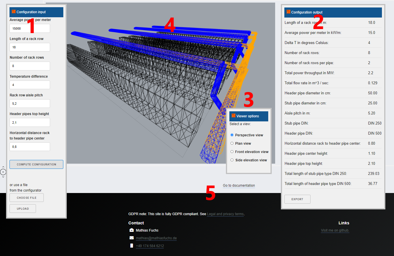
The usage of the web app should be quite self-explanatory.There are three "windows" that can be dragged with the mouse labelled (1), (2) and (3) in the screenshot above.
There is a main 3d windows labelled (4), and a link to the documentation (5).
The first window (1) is the window governing the configuration parameters and the submit button. In the future, there will also be an upload button to import geometrical constraints and outer dimensions of the building from the configurator. Second, there is an output window with the resulting configuration parameters. In the future, there will be a save/export button to save a configuration directly to Revit / construction documentation, to web export, or to Excel etc.
The window (3) allows to switch between plan view, front and side elevation view.
Navigation
Mouse left: panMouse wheel: zoom
Mouse right: move
Functionality, physics and underlying abstract class layout
The code works basically by performing the following steps:- Calculate the power of the whitespace
- Calculate the volume flow using the formula P = Q rho c deltaT where P is power, rho is the density of water, c is the heat capacity of water, Q is volume flow, delta T is the temperature difference between hot and cold water.
- Calculate the ideal pipe diamters from the volume flow rate assuming a maximal effective water speed of 1m/s.
- Choosing the smallest larger DIN diameter for the stub pipe and the header pipe.
- Assemble the 3d output.
Next plans, further options and next steps, opportunities ....
- Import from configurator
- Export into configurator
- Export to Revit
- Export to Excel
- Incorporation of cable layout
- Extension to multiple floors